Development of custom electronic boards with CNC Router.
For the development of the group project corresponding to week 3, focused on "Computer Controlled Cutting", I organized a trip from Huanuco to the city of Lima. The main objective of this visit was to carry out the detailed characterization of various parameters of the laser cutting machine, such as focus, power, speed and purpose free space of the joints. These aspects were fundamental for the correct execution of our project.
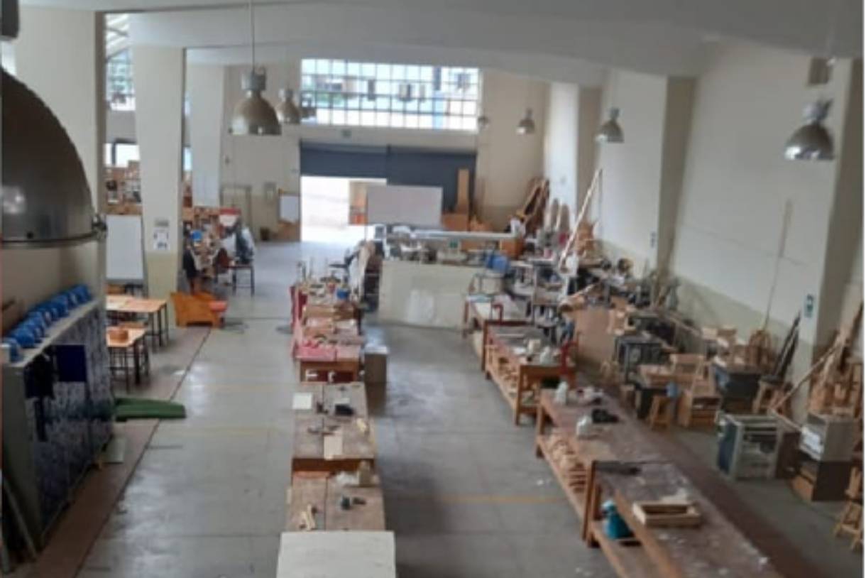
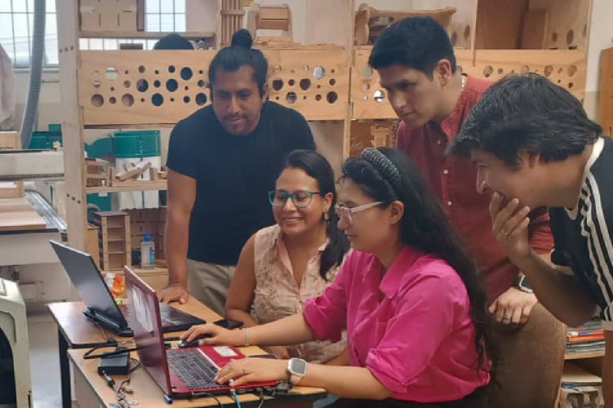
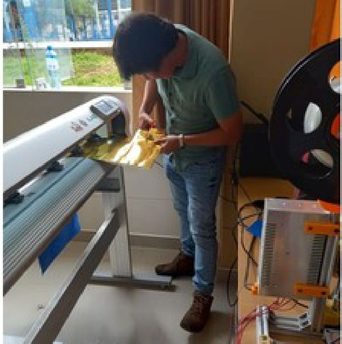
During my stay in Lima, I had the privilege of working at the FabLab iFurniture facilities. It was an enriching experience, as the FabLab iFurniture team welcomed us and gave us full access to their resources, including the laser machine needed for our collaborative work. The opportunity to test and work as a team in such a collaborative and well-equipped environment was invaluable to the success of our project.
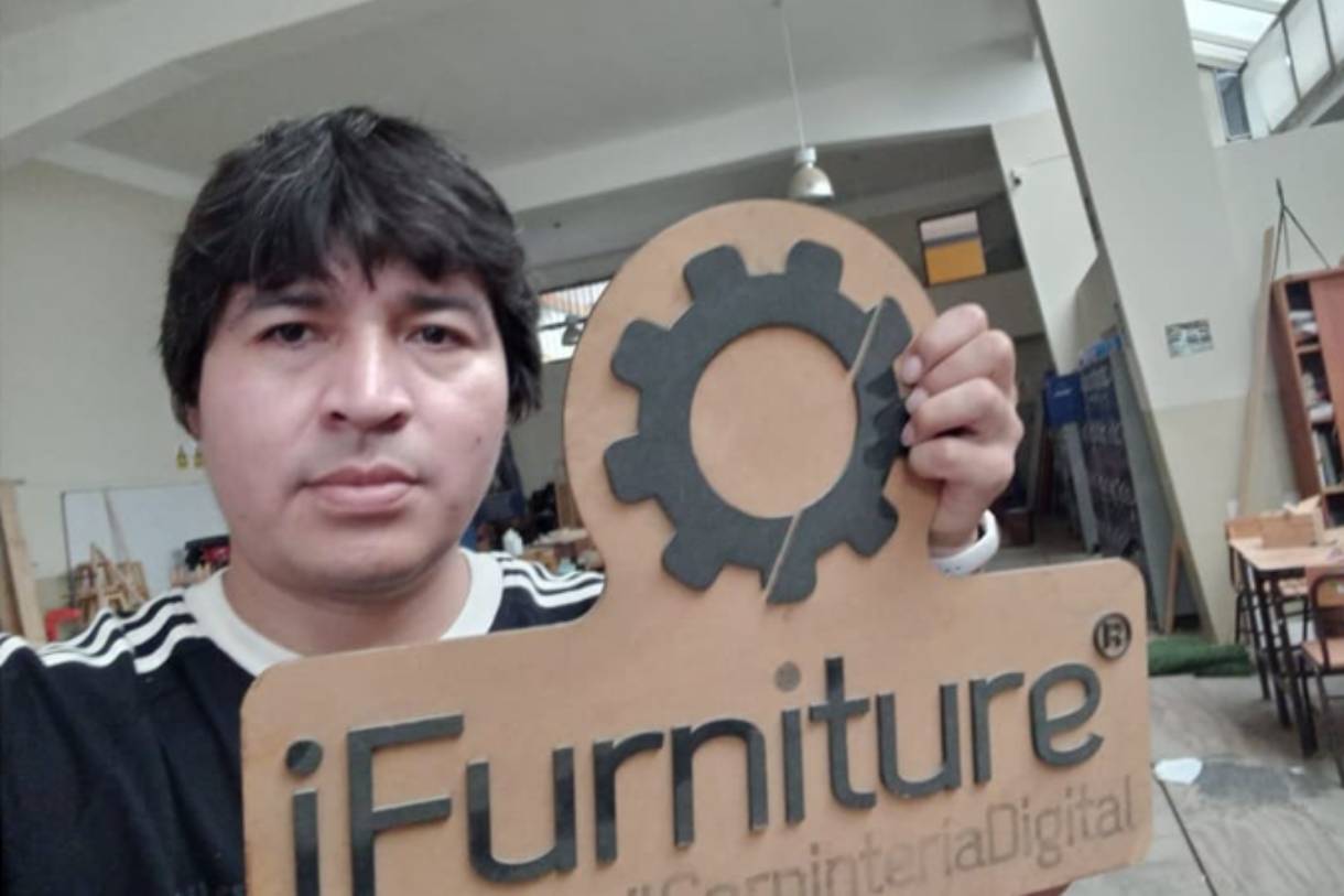
At Fablab iFurniture
Fablab iFurniture
I take this opportunity to express my sincere gratitude to FabLab iFurniture for their generous hospitality and willingness to collaborate. The collaboration between FabLab iFurniture and FabLab Perú demonstrates the spirit of community and cooperation that drives the movement of digital manufacturing laboratories throughout the country. I am grateful for the opportunity to participate in this unique experience and for the lessons learned that will undoubtedly enrich our future projects at FabLab Peru.
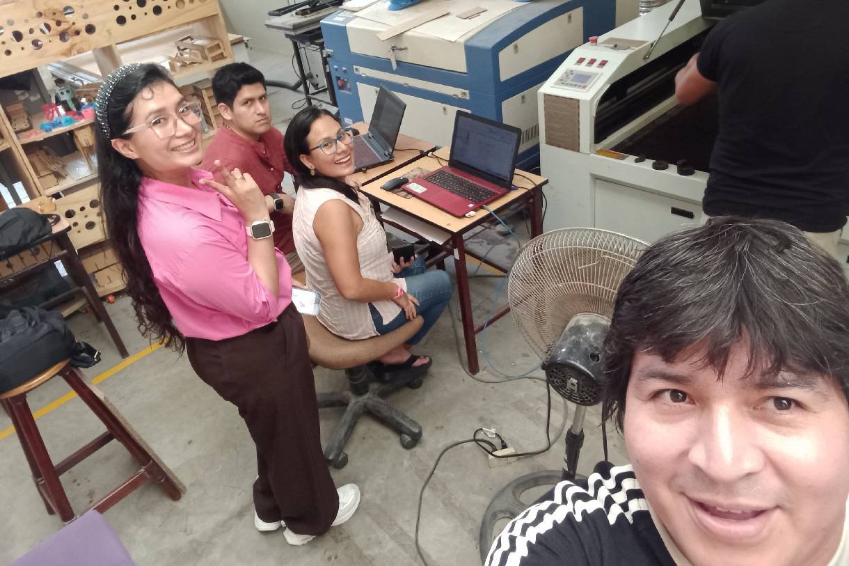
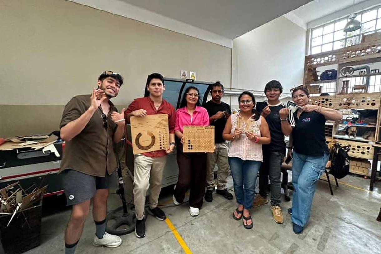
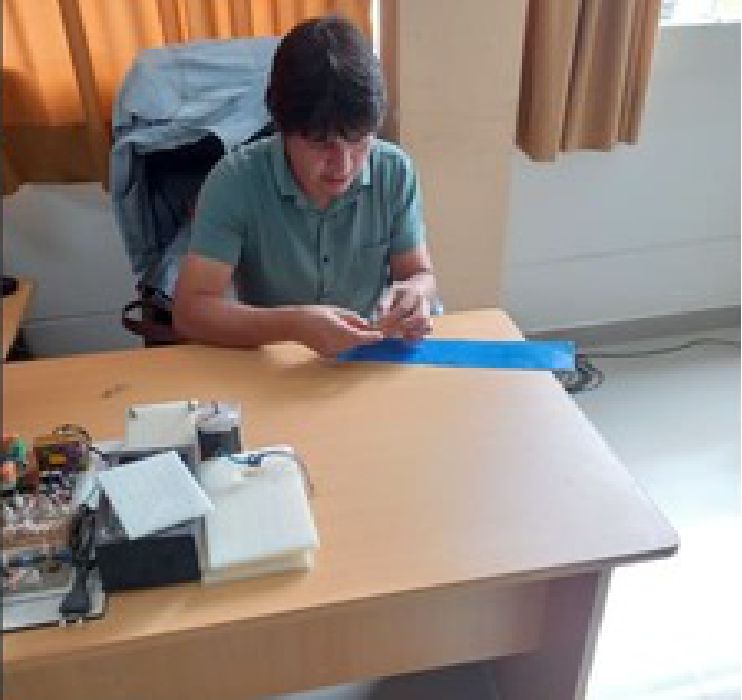
Teamwork
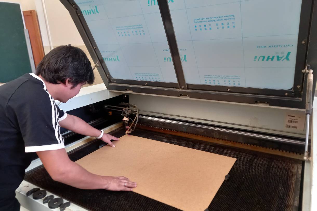
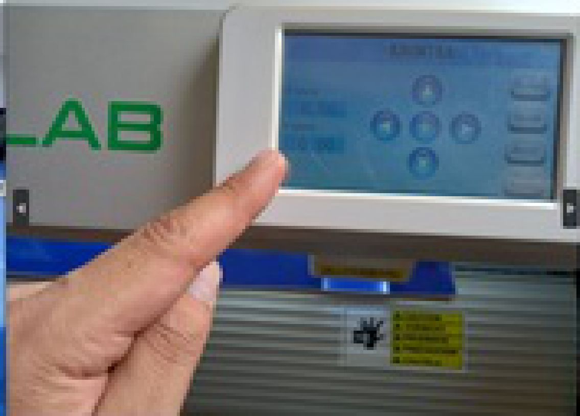
The aim is to provide detailed instructions for making computer controlled cuts using the C4V LASER 1390 laser machine. Cutting parameters including speed and power as well as calibration of the laser head with respect to the 3mm MDF material will be covered:
Teamwork
Take these recommendations into account.
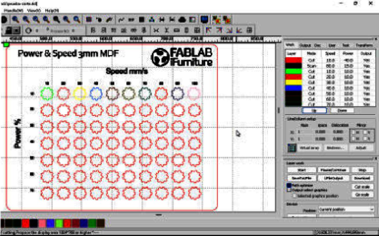
Experimenting with the laser machine on cuts of 3 mm thick MDF material, it was observed that different combinations of speed and power influenced the final result. For example, at lower speeds of 10 mm/s, better cutting results were obtained compared to higher speeds of 20 mm/s. In addition, it was evident that increasing the laser power from 40% to 60% improved cutting efficiency, although this was affected by the speed of the machine.
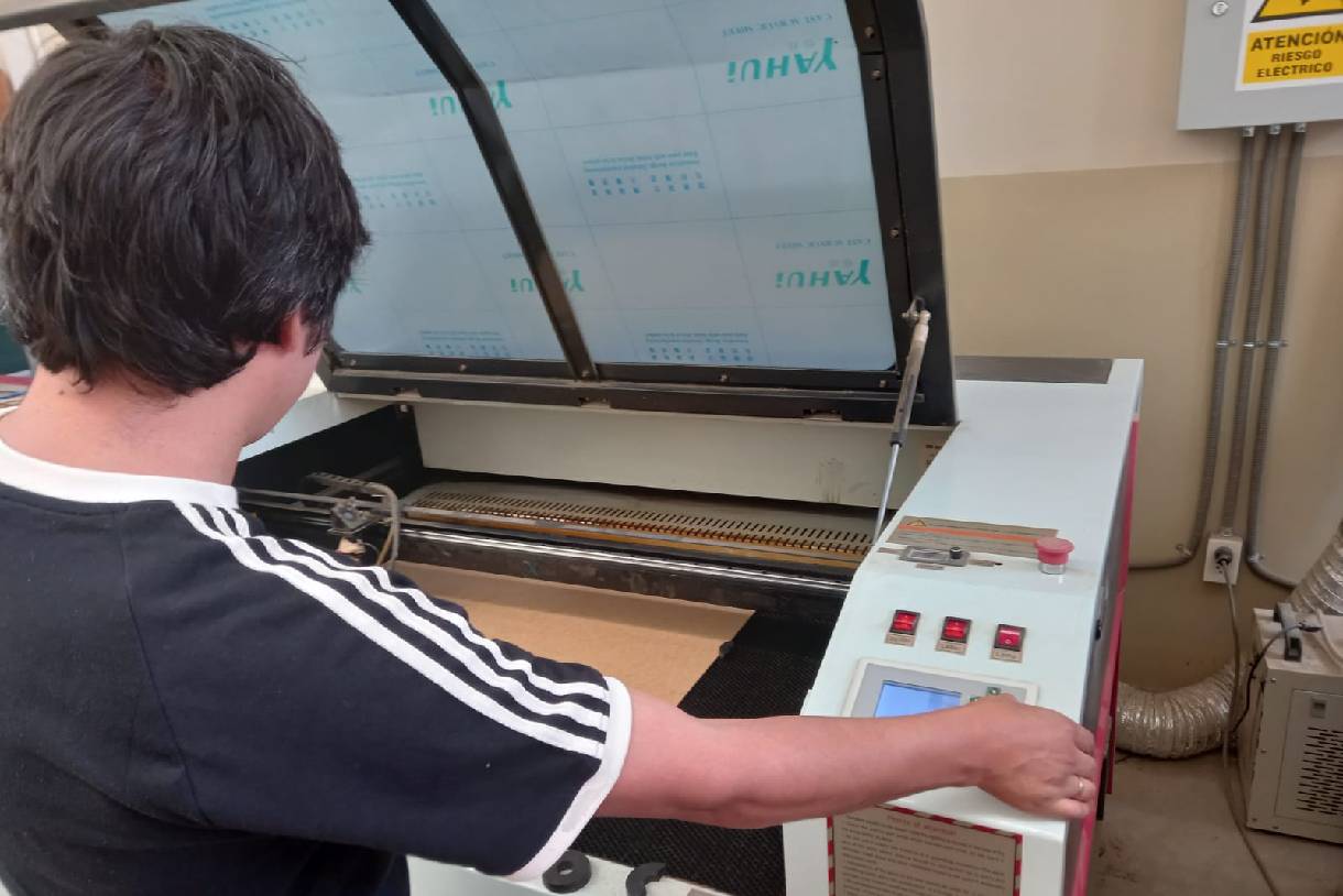
Locating the machine
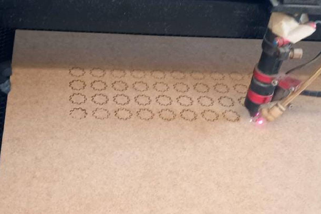
Cutting tests
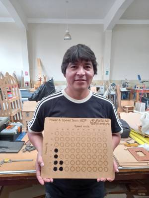
Carrying out a complete die process, varying both speed and power from minimum to maximum values, allowed us to understand the relationship between these parameters and their effect on the cutting process. It was observed that, within the range tested, the optimal combination of speed and power to obtain clean and precise cuts in 3 mm thick MDF material was 10 mm/s with a power of 60%.
This was the result of the first test carried out with the C4V laser 1390 machine.
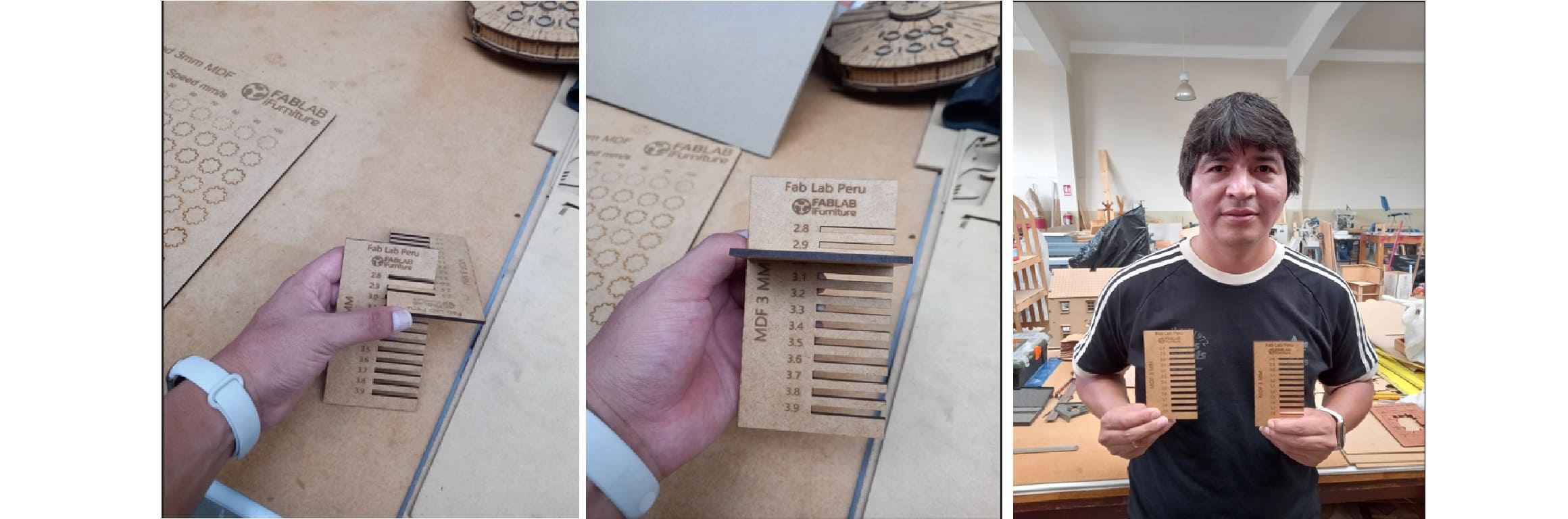
In addition to our initial tests, we decided to perform a second evaluation focused on the coupling between two combs. This research phase is crucial to ensure the effectiveness and precision of our products in practical applications. To carry out this evaluation, a comb was designed with specific cuts of various dimensions: 2.8 mm, 2.9 mm, 3.0 mm, 3.2 mm, 3.4 mm, 3.6 mm and 3.8 mm.
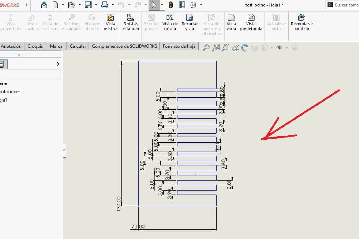
The reason behind this variety of dimensions lies in the need to find the most precise and effective fit between the two combs. Understanding how these parts interact in terms of coupling is essential to maximize performance and utility when performing our future jobs. Therefore, after designing the comb with specific cuts, we proceeded to carry out a series of exhaustive tests to determine which of these measures offers the best fit between the two combs under evaluation.
During the testing process, special attention was paid to details such as coupling stability, resistance to deformation and consistency under different loading conditions. These criteria allow us to evaluate not only the effectiveness of the coupling in terms of physical fit, but also its ability to withstand adverse conditions and maintain its functionality over time.
In summary, this week has been an enriching experience in which we have combined teamwork, technical experimentation and the creativity of each one of us, which was of great importance to achieve outstanding results in our weekly task.
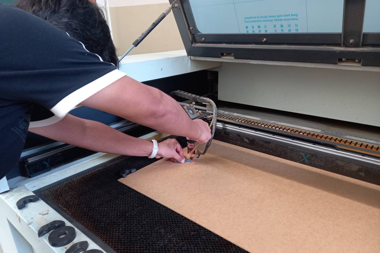
I understood the importance of meticulously calibrating the laser machine, precisely adjusting speed and power parameters to optimize both cutting efficiency and precision. This stage has proven to be crucial to ensure consistent and high-quality results in our projects. In addition, it is essential to close the lid of the machine during the process to avoid inhaling the smoke generated. It is also essential to check that the machine bed is level throughout its entire length, as this will help ensure uniform engraving and cutting.
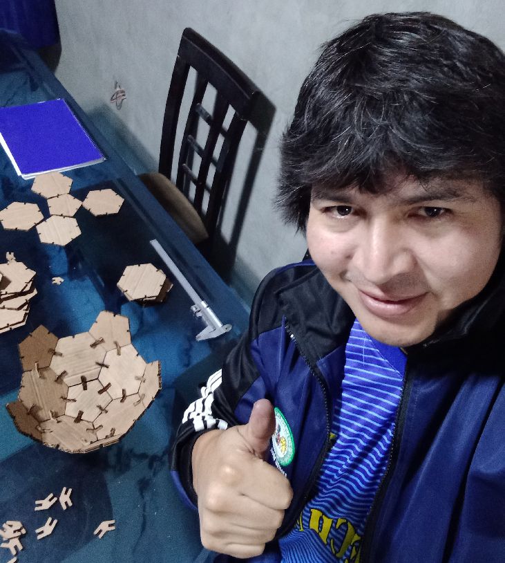
For my individual project, on Saturday morning I took a trip to the city of Huánuco, where I currently reside, with the purpose of dedicating the necessary time and completing this task in a comprehensive manner.
I started using the laser machine I have at home to carry out the parametric cuts of the hexagons and pentagons, with which I would later build models. This process gave me the opportunity to adjust the cutting parameters in a precise and personalized way, ensuring the quality and accuracy required for my designs.
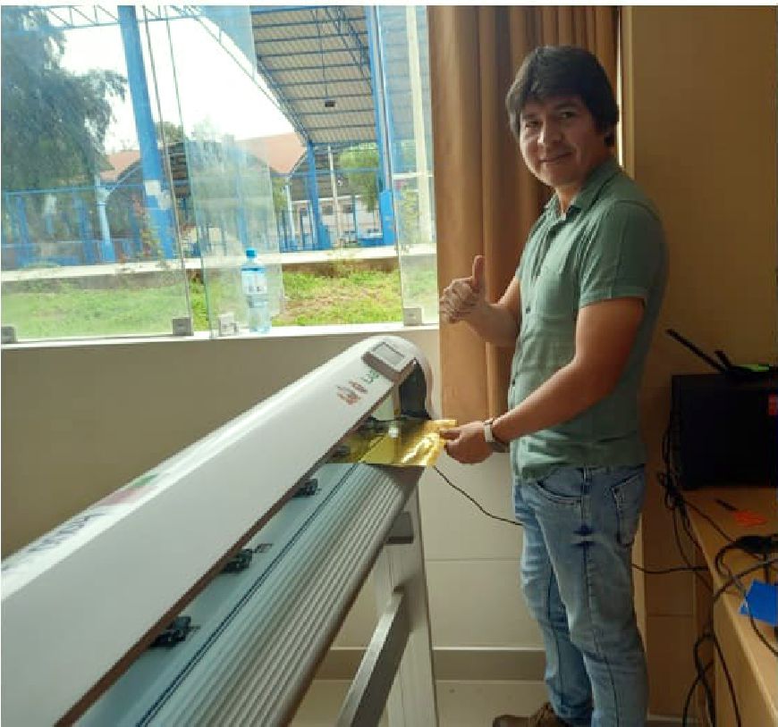
Next, I moved to FabLab Unheval, where I was able to access their advanced vinyl cutting machine. Here I cut the logo of FabLab Perú and FabLab Unheval and I also thank you for collaborating with me and thus being able to finish my task for this week
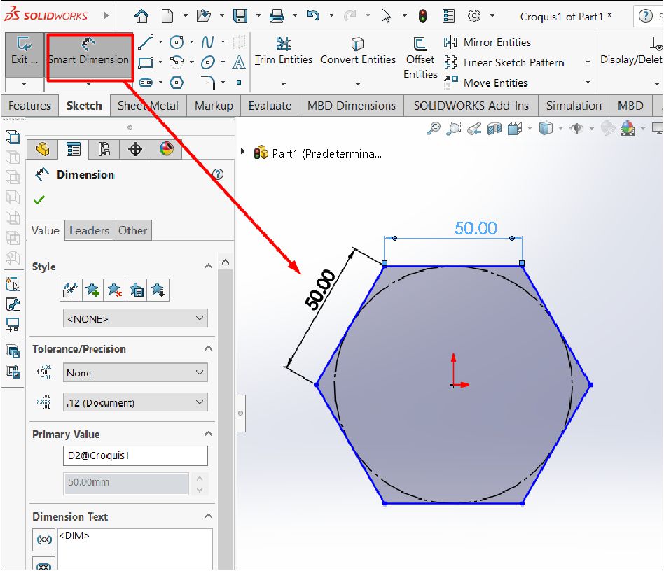
To initially carry out the design and do personal testing, standard side measurements of 5 cm were established for pentagons and hexagons, providing a uniform basis for study if you want to make a ball. SolidWorks parametric functionality was then used to model these polygons, allowing for dynamic manipulation of their dimensions and properties.
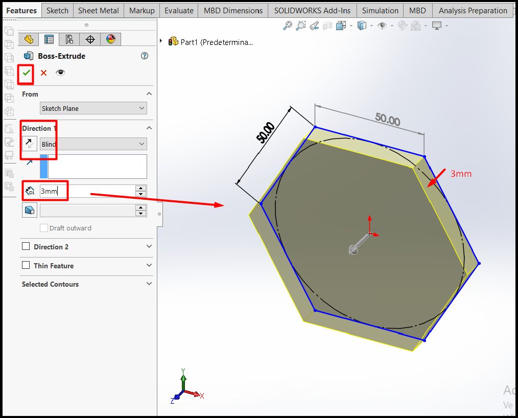
Once you have the three-dimensional solid of the hexagon, the next step is to design the inserts on each of its sides, which will have a thickness of 3 mm.
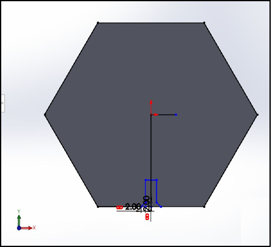
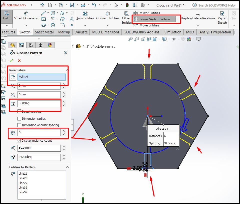
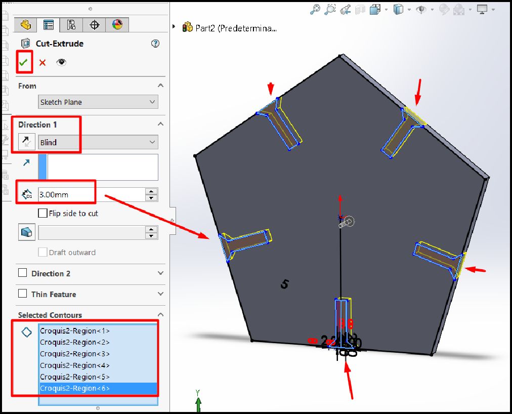
The design of the socket is carried out in the plane, on one face of the hexagon, and then the cutting operation is carried out to now have the solid with the socket sockets.
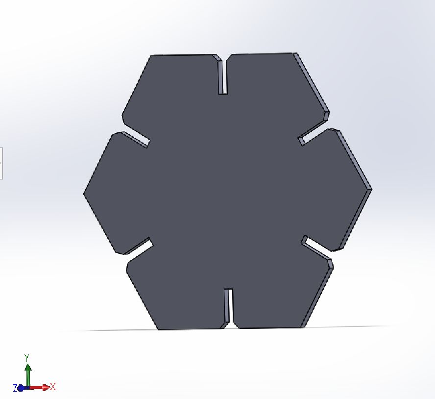
The image shows the completely finished solid, prepared for simulation, and also shows the cut of the piece to clearly visualize the inserts on each side of the hexagon.
For the following image, we only need the reference of one of the sides, which has a length of 50 mm. Next, we will proceed to place this measurement in the image.
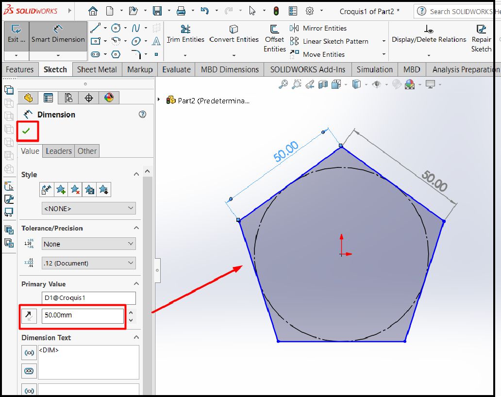
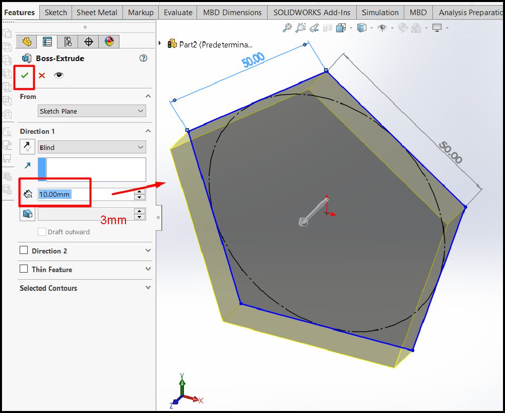
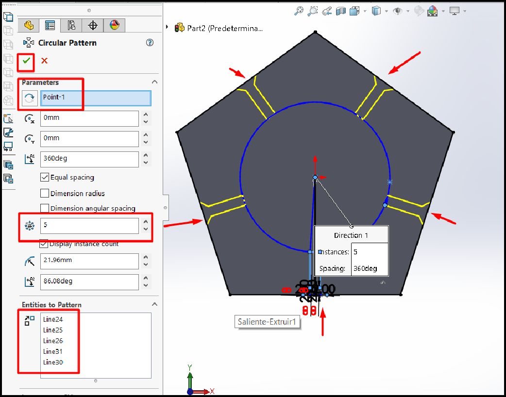
After having extruded the solid, the next step is to create a sketch near the five sides to be able to design the inserts and make them fit correctly.
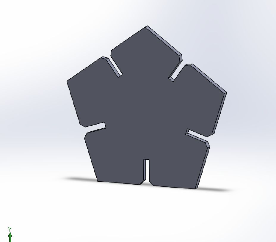
The pentagon design is complete and ready to be modeled on and then cut using the laser machine.
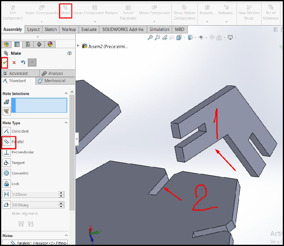
It's time to create the third piece. To do this, we take the design of the hexagon as a reference, especially the angle, to ensure uniformity once it is assembled.
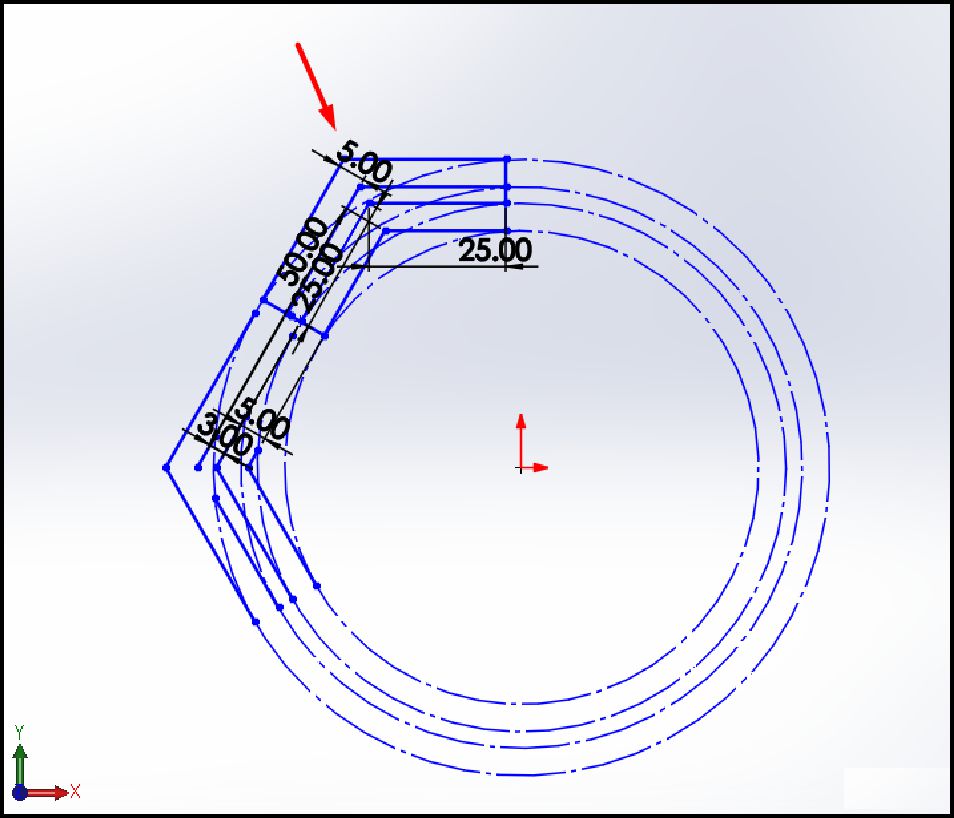
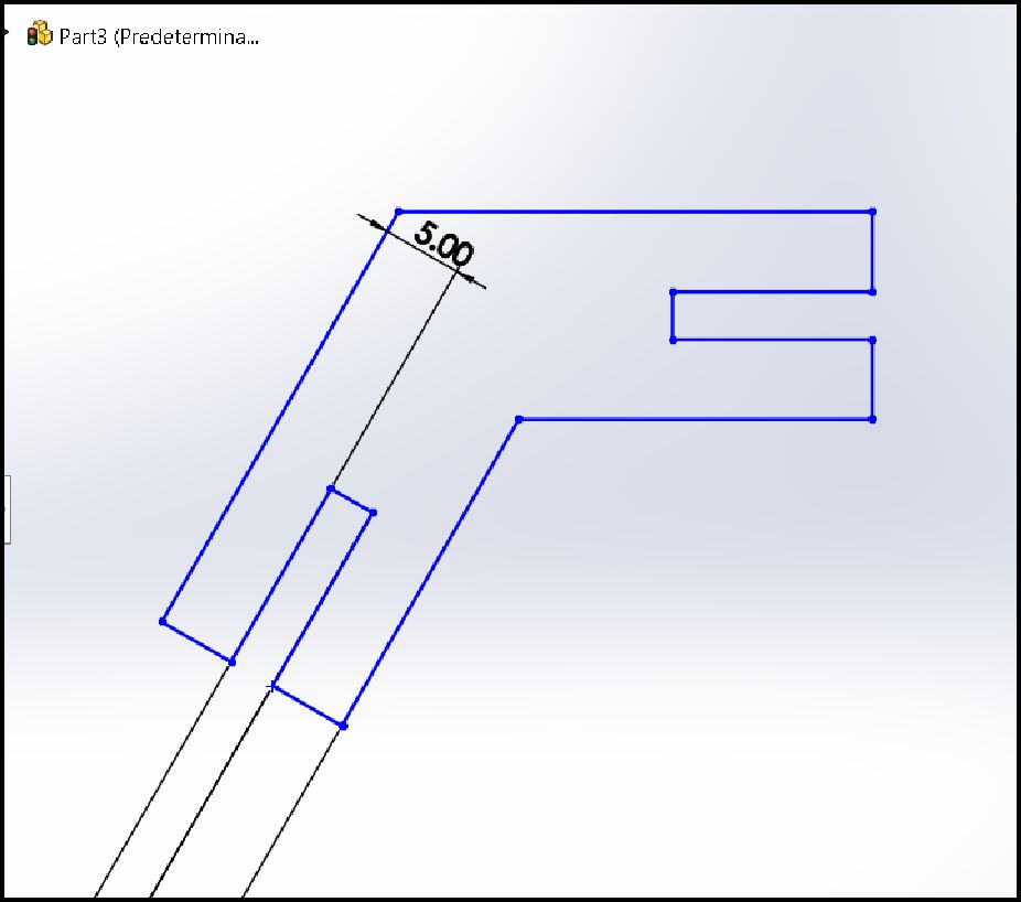
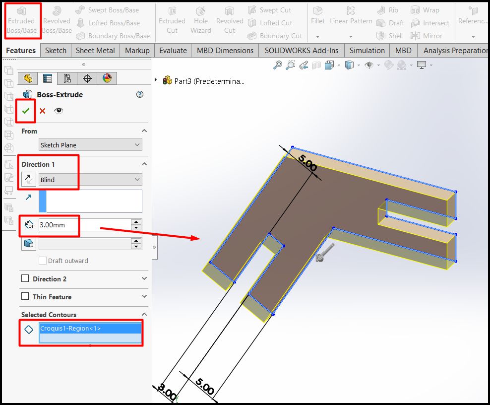
As we mentioned previously, we proceed to make the sketch using the hexagon as a reference. Once the sketch is completed, we extrude the part to 3 mm thickness, according to the thickness of the material.
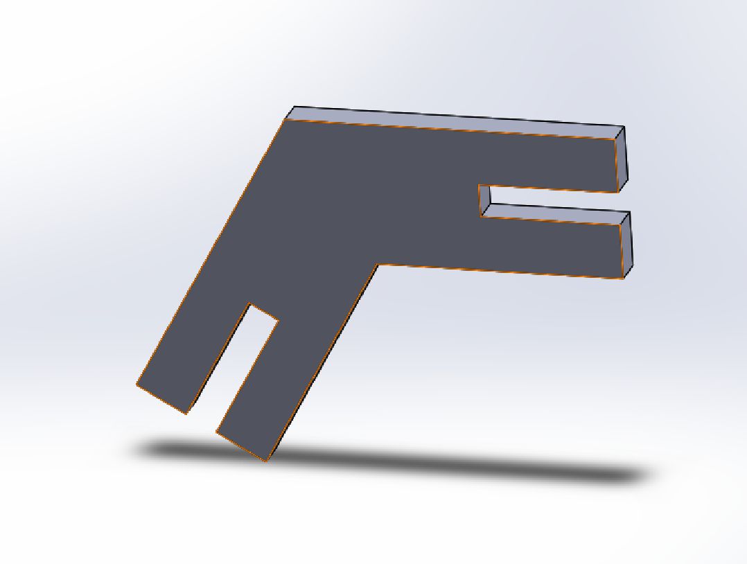
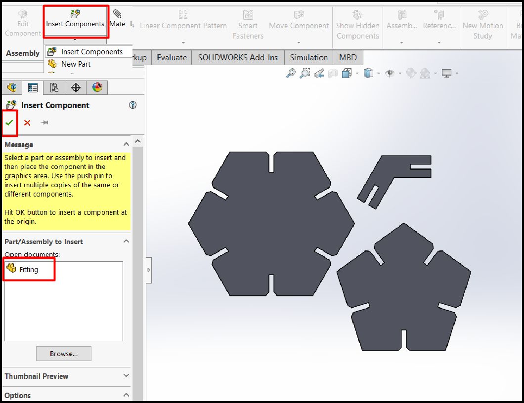
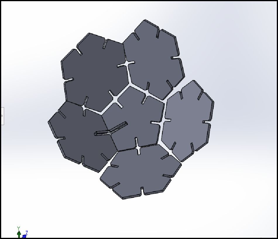
Once all the parts have been designed, the next step is to create the assembly to visualize what our final model will look like. This will provide us with a reference to identify any aspects that need improvement.

Using the LightBurn software to preprocess the images that will be cut with the S9 laser, I proceeded to configure the parameters according to my needs. In this case, I set a cutting speed of 100 mm/s and a laser power of 60%, suitable for cutting cardboard material with a thickness of 3 mm. These specific settings ensure a clean and precise cut, optimizing the production process and guaranteeing high quality results.
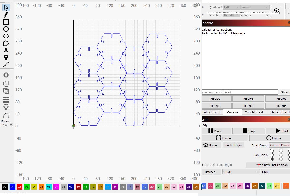
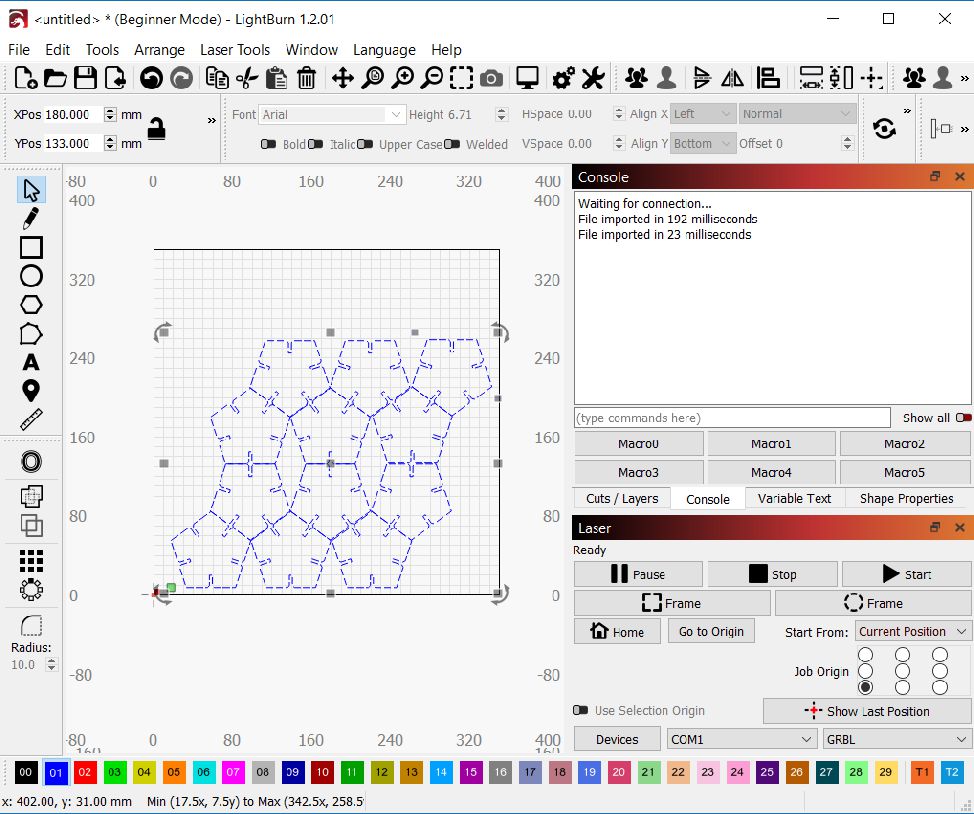
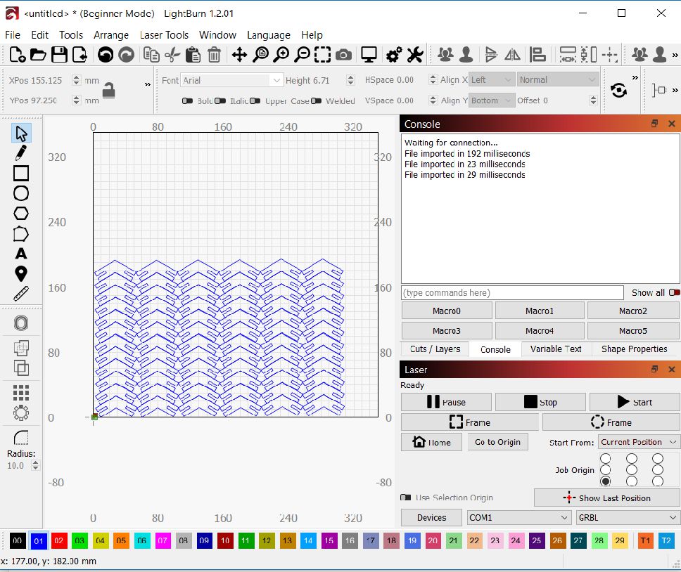
The cutting process is simple and direct. You just need to have the cutting parameters configured according to your needs. Next, select the starting point of the cut, choose the piece you want to cut and click the 'Start' button. With this action, the laser will begin to execute the cut in an automated and precise way.
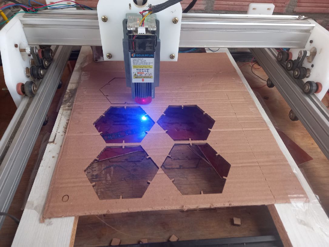
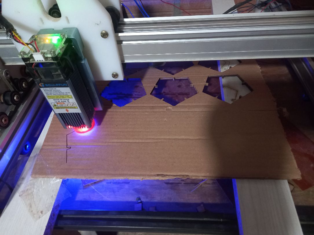
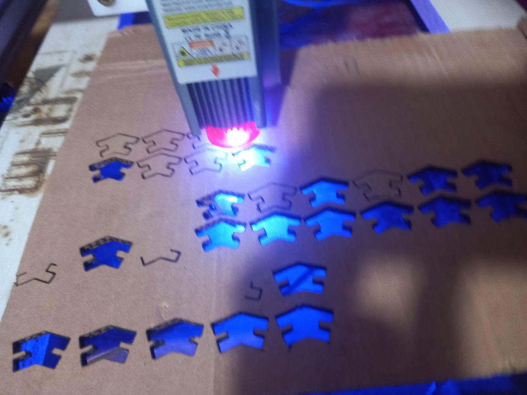
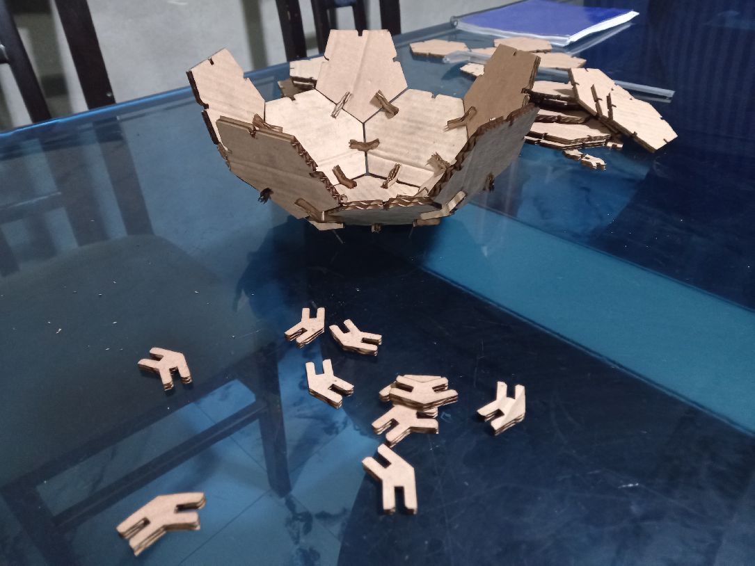
This process is repeated until the cutting of all the necessary figures is completed. All you have to do is wait for the laser machine to finish its work. In this particular case, 20 hexagons, 12 pentagons and 70 couplings will be made, which will guarantee the production of all the parts required for the task.
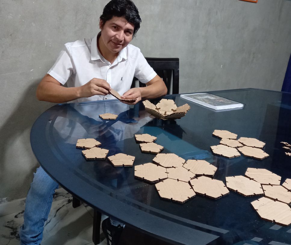
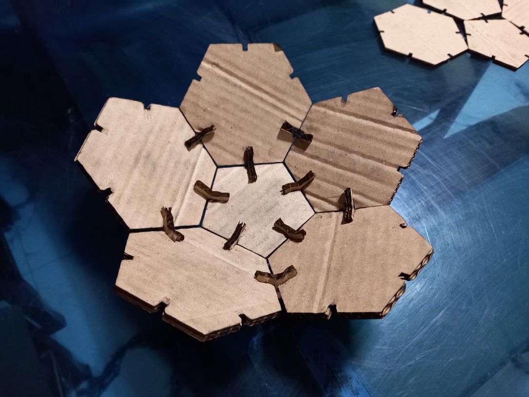
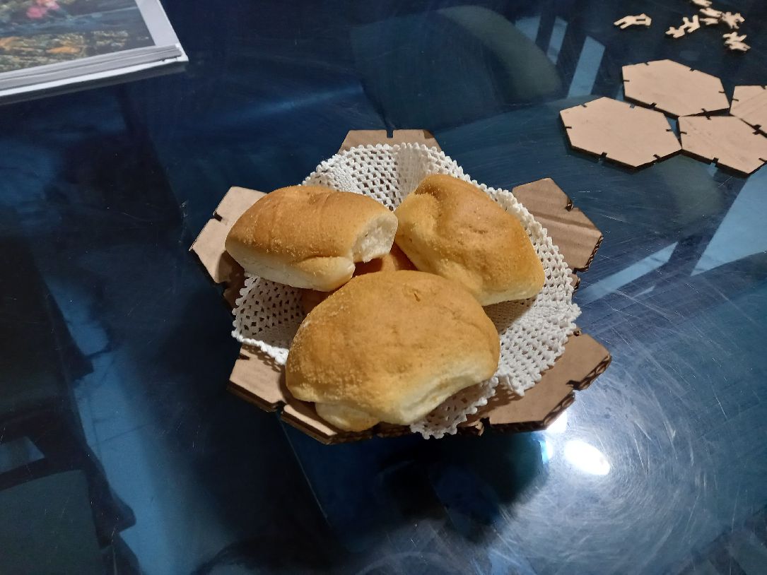
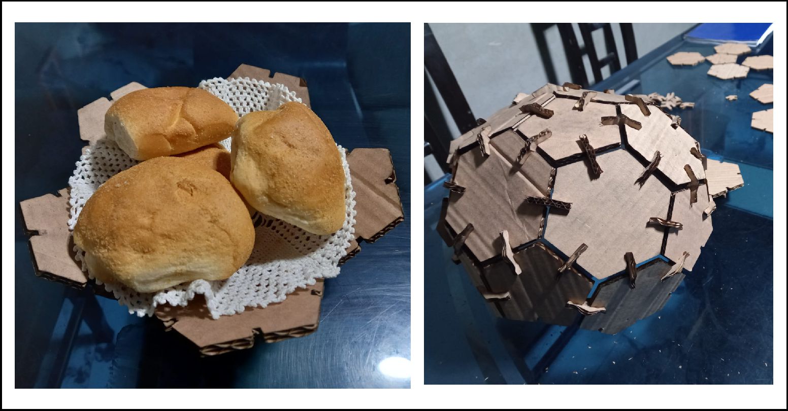
The final step is to assemble the hexagons, pentagons and couplings to shape the complete figure. This assembly process is essential to join all the pieces properly and obtain the desired final result.

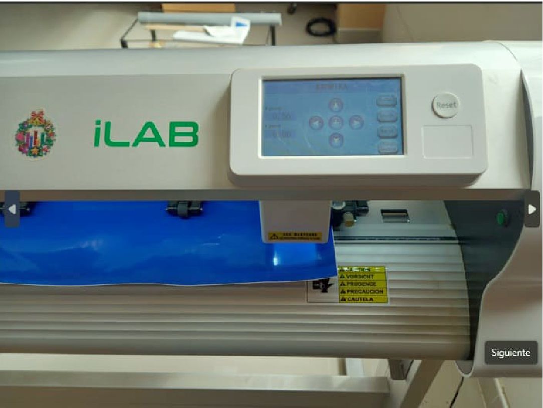
Para trabajar con vinilo, utilicé el plotter CY1200, el cual cuenta con las siguientes características:
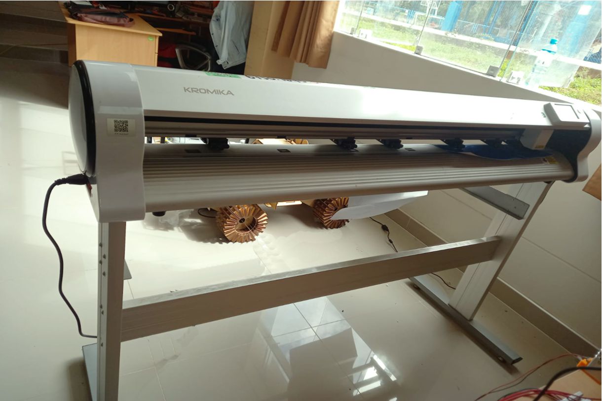
Before proceeding with the cut using the Vinyl machine, it is important to mention the brand, model and cutting area of the equipment. In this case, we will use a Kromica brand machine, model CY1200, which has a linear cutting size of 1200 mm.
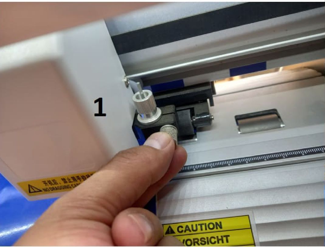
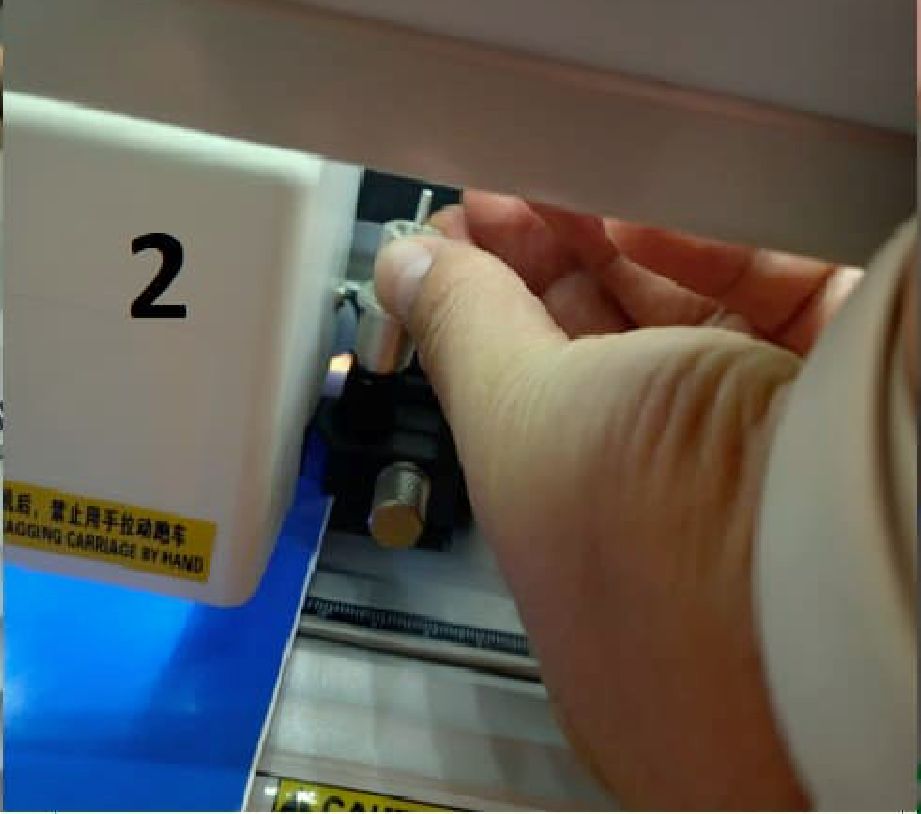
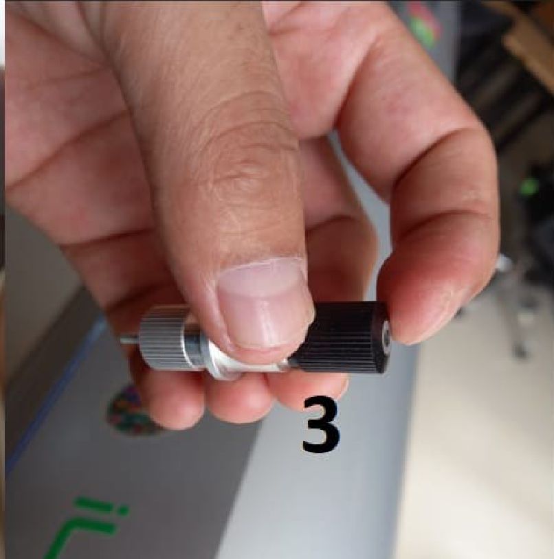
The optimal setting for the cutting depth of a vinyl plotter blade can vary depending on the type of vinyl and the model of the plotter. However, as a general rule, the blade should be adjusted so that it only cuts through the vinyl and not through the contact paper backing. This means that the blade should be set deep enough to cut the vinyl, but not so deep that it cuts the paper backing.
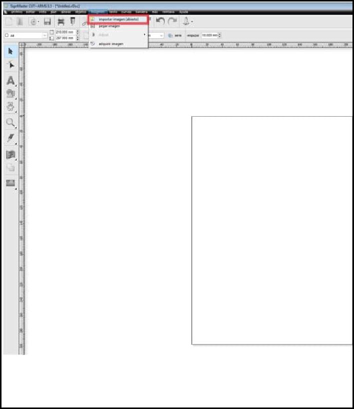
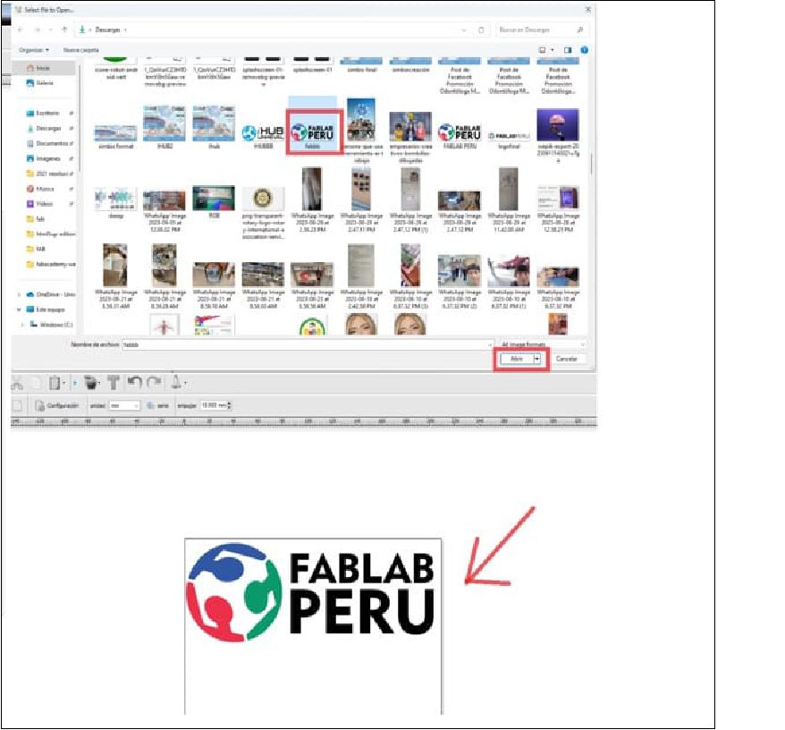
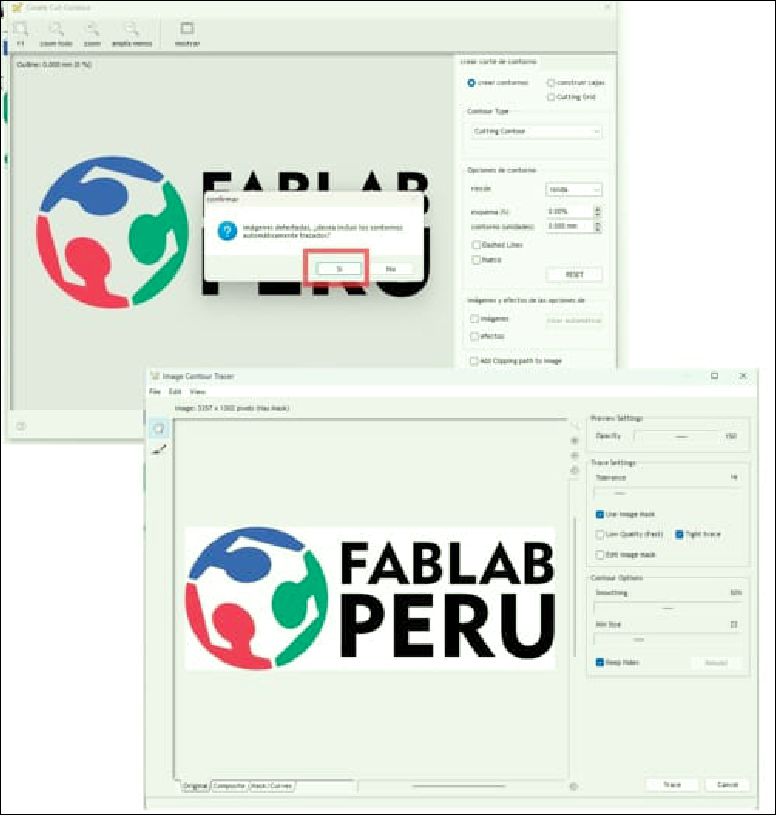
After you have prepared the physical part, the next step is to open the corresponding software of the machine. In the toolbar, proceed to import the image you want to cut.
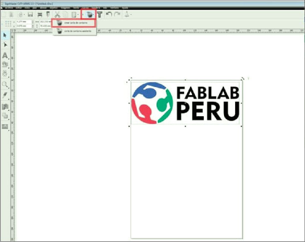
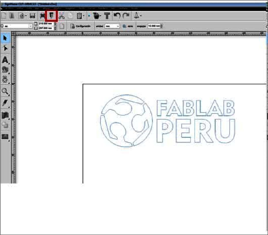
Once the desired image has been imported, the next crucial step is to generate the cutting contour in the software toolbar. This step is essential, especially when you want to cut only the outline of the figure, without including the interior filling. By creating this cutting contour, you precisely define the path that the plotter blade will follow, ensuring that the vinyl is cut to the exact shape desired. This process allows for greater efficiency and precision in production, as any excess material is eliminated and the use of vinyl is optimized. Therefore, creating the cutting contour is not only a technical step, but also an integral part of the workflow that ensures high-quality results in the vinyl cutting process.
Once only the edge of the desired figure has been obtained, the next step is to carry out the cutting process, following the instructions provided in the software interface. This crucial step involves correctly setting cutting parameters, such as blade speed and pressure, to ensure a precise and clean cut. By carefully following the instructions and properly adjusting the cutting plotter settings, you ensure that the vinyl is cut to the exact shape desired, without compromising the quality of the final result. This process marks the critical point in production, where precision and attention to detail are essential to achieve an optimal finish on the cut vinyl.
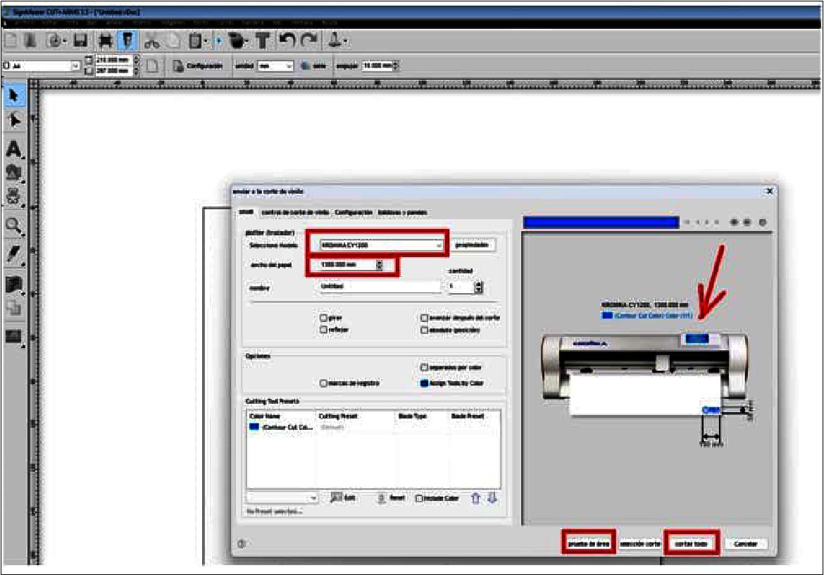
Once all the necessary software settings have been configured, the next step involves physically preparing the machine. This includes carefully placing the material to be cut on the work surface, ensuring that it is securely fastened with appropriate latches to prevent unwanted movement during the cutting process. It is crucial to visually verify that the "X" and "Y" axes are properly aligned at zero, ensuring an accurate starting position for the cut. Once everything is ready and confirmed, we proceed to start the cut through the software, pressing the designated command to begin the process. This step marks the beginning of the physical work, where the machine will execute the instructions established in the software to cut the material into the desired shape. It is essential to carry out these steps with attention and precision to guarantee optimal results in the cutting process.
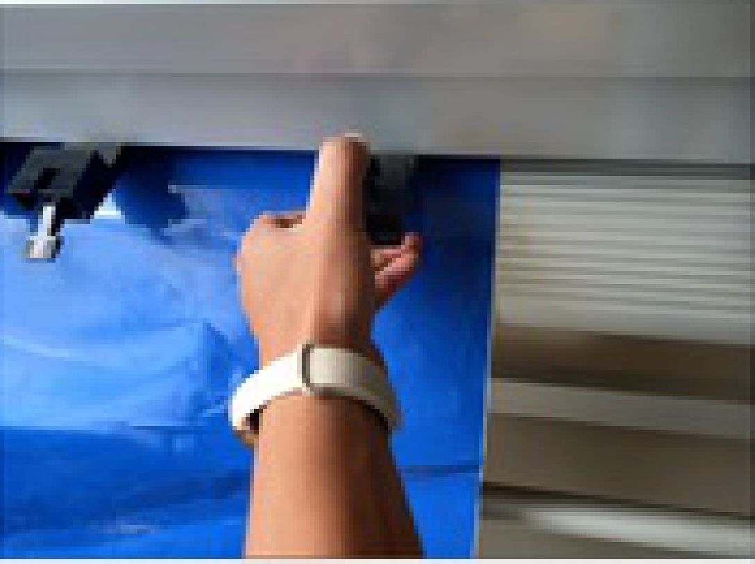
After completing the cutting process, the task of accurately removing the cut figures from the cutting surface proceeds. This step requires attention and finesse to avoid damaging the freshly cut pieces. Once the figures are free from the cutting base, they can be given a quick inspection to ensure that the cut has been completed satisfactorily and that there are no loose pieces or unwanted areas. Then, these figures are placed in the desired material for their application.
After completing the cut with the vinyl machine, the next step involves carefully removing the desired image and then adhering it elsewhere. In my case, this meant removing only the Fablab Perú logo, which I intended to paste in my notebook. This process requires precision and attention to ensure that the image is transferred cleanly and without damage to the new medium, thus providing a flawless final result.

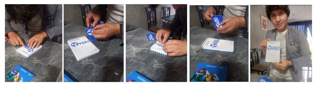

As you can see in the following image, I only remove the desired letters and logo from the cut vinyl, which results in a spectacular presentation. This selective focus highlights the image effectively, ensuring a clean and professional presentation.
Teamwork stands as a vital component in our process, allowing us to merge experiences and approach tasks more efficiently, which translates into a notable reduction in the time required for their execution. During our collaboration, we have come to the conclusion that regular maintenance of the machine is essential to ensure its optimal performance. Among these maintenance tasks, periodic cleaning of the mirrors emerges as a crucial activity to preserve the precision of the laser. Likewise, we have recognized the importance of meticulously checking and leveling the work platform, as this simple but essential step contributes significantly to obtaining satisfactory results in our cutting projects.
Development of custom electronic boards with CNC Router.
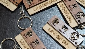
Development of personalized keychains and ornaments with CNC Laser.
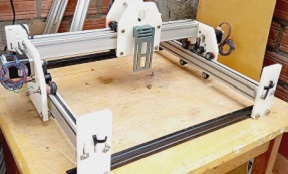
Development of custom machines "Desktop CNC Laser.

Huánuco is a Peruvian city, capital of the district, province and department of the same name in the north-central area of the country. The city has a population of 235,529 inhabitants. .